Decoding COBie: Understanding its true purpose in AEC

Decoding COBie: Understanding its true purpose in AEC

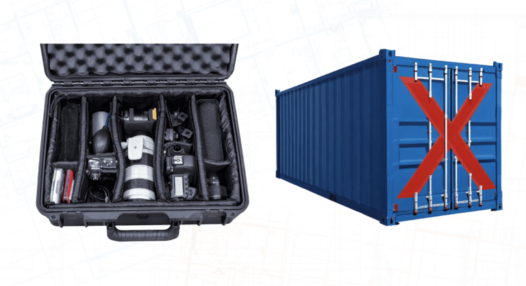
COBie is the opportunity for the supply-side of designers and constructors to deliver to the owner/operator the information needed to operate and maintain their facility from day 1. It can be thought of as a simple suitcase with the foam inserts with a place for everything needed with no wasted space or danger of the contents rattling around. It isn’t a 40ft shipping container you can fit (almost) anything into. But it is always an “information exchange” – a transaction that delivers information. Unfortunately, people have often projected all sorts of other expectations onto COBie, making success harder. 

Let’s look at some things that COBie is NOT, and why…

1. COBie is NOT a portfolio, asset or facility management application. COBie stands for “from Construction into Operations of Buildings – information exchange”. As an experience-hardened colleague once explained it can equally stand for “Can’t Operate a Building in Excel”. The point of a structured information exchange is to let suppliers collect the information without worrying about the owner/operators applications – which may be unknown or change.
2. COBie is NOT a digital twin. It is a snapshot taken at handover of the information held by the Constructor. Any additional drops prior to that are waypoints towards that handover. The only reason for preparing a COBie delivery package is if it is going to be loaded into an owner/operators application(s). 

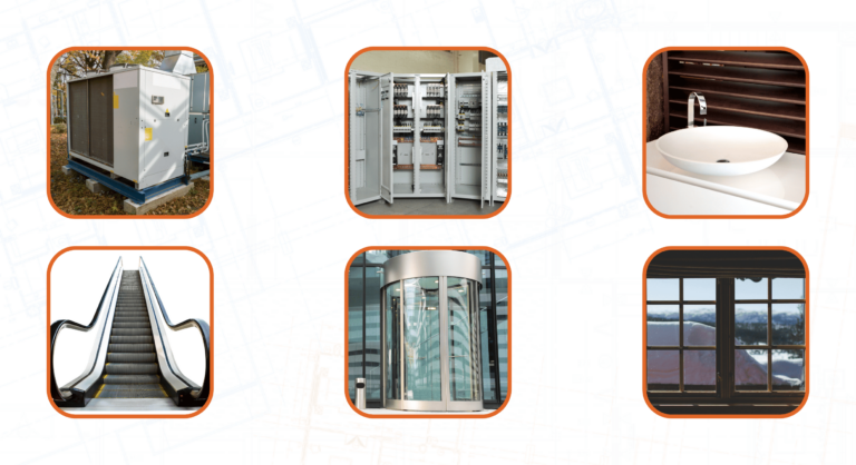
3. COBie is NOT a Building Information Model. It only represents equipment, such as mechanical, electrical, plumbing and transport devices, and, on the structure and fabric side, only doors and windows, along with the context to find and identify them.
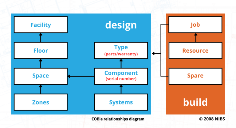
4. COBie does NOT need any specification of the equipment to be included. NBIMS v3 p215 gives a sufficient list of exclusions – in ISO19650 terms, NBIMS v3 standard IS the Exchange Information Requirement. COBie does NOT need to have the required attributes (properties) specified. Again, NBIMS v3 is sufficient. For example, only things that have a classification and a unique name are even candidates to be included. COBie does NOT need to be specified for relationships. Yet again, NBIMS v3 is sufficient, as it defines the cross relationships needed. Any piece of equipment must be related to a product Type and a Space . The Space must relate to a Floor. The product Type must be related to its Jobs and Spares.  

5. COBie does NOT need to have the required attributes (properties) specified. Again, NBIMS v3 is sufficient. For example, only things that have a classification and a unique name are even candidates to be included. 

6. COBie does NOT need to be specified for relationships. Yet again, NBIMS v3 is sufficient, as it defines the cross relationships needed. Any piece of equipment must be related to a product Type and a Space (or location) . The Space must relate to a Floor (or region). The product Type must be related to its Jobs and Spares.  
7. COBie does NOT have to be a spreadsheet. OK, it usually it is, as this is the most obvious way of making it checkable on the supply side and readable on the receiving side. An alternative is the subset of IFC defined in NBIMS v3.

8. COBie does NOT need to use Excel. It uses any spreadsheet software that supports using the open XLSX format which is a compressed XML. XLS is not COBie.

9. COBie does NOT necessarily come from BIM. Much of COBie should be in BIM by the end of the design stages but some of it just can’t be. The gathering of Contacts, Documents, and Jobs, Spares and Resources may have to be managed separately. Luckily, there are tools to merge spreadsheets.

10. COBie is NOT an isolated deliverable. It must include the schedule of associated documents , such as general arrangement drawings associated to Floors and Spaces or product data associated to Types.

11. COBie design sheets can NOT be exported from BIM, until you have added classification to Facility, Spaces and Types.

12. COBie does NOT have to contain US Omniclass. In the UK Uniclass is part of the UK Government Information Mandate and the UK National Annexes to the ISO19650 standards. There aren’t many other classifications systems that cover both Spatial and Physical objects.

To sum up, its vital to develop a repeatable process for creating COBie. That process must accurately filter your information, check for omissions and then lay it out exactly as required. COBie can be easy and it makes for a better handover!

Missed our webinar, “How to enhance your COBie design worksheet?” ft. Nicholas Nisbet and Ward Turkyeh?!

Sign up today for your exclusive session and acquire technical knowledge about COBie implementation!

Contributor

Owner at AEC3 and
Vice Chair at BuildingSMART UKI

Owner at AEC3 and
Vice Chair at BuildingSMART UKI

F1 applied to Design + Construction

F1 applied to Design + Construction

There is nothing quite like the moment of elation when you have become a champion. It is a brief moment of perfection that is the culmination of smart work, determination, deliberate practice and flawless execution. When you talk to champions, they all talk about the little things they focus on the attention to the details. Those details often deal with time; hours, minutes, seconds, hundredths or even thousands of a second can be the difference between a championship and second place.

Anyone who follows Formula 1 knows the phenomenon: everything revolves around seconds or less. During qualifying, a fraction of a second is crucial: it makes the difference between pole position and 6th or 7th place. But during the race, this difference can be as much as two laps. Why this difference?!

There are several reasons for this. Consider strategic choices made by teams around fuel and tyres, position on the grid and the driving style of the driver. In short, qualifying is all about maximum speed for a short period of time, while the race itself is a long and complex battle, where numerous factors influence drivers’ performance. Every second determines not only the difference in qualifying, but the entire course of the race.

Parallel to Design + Construction

In F1 each team designs their car to meet specifications and criteria laid down by the FIA and in Architecture the designers design a structure to meet the specifications of the client and the Authorities having jurisdiction over the location where it is going to be built.

Each F1 team must then construct the design which is often 16,000 pieces in a set duration to meet the racing season and in Architecture the contractor must contract and build the structure, which can be millions of pieces, in a set duration to meet the contract requirements.
F1 is the mixture of design, engineering, human physical performance, data science, heuristics, teamwork, money, and guts. Design + Construction is the mixture of design, engineering, human physical performance, data science, heuristics, teamwork, money, and guts.
In Design + Construction, very few have ever done the math that 8 hours = 28,800 seconds and that a $ 21,000,000 month in Work In Place equates to $1,000,000 per day divided by 28,800 seconds = $ 34.72, but there are a few who are striving for that championship who done the calculations.

In F1 superior design reduces defects that slow the assembly of the car through lost time of rework or slow the car during a race because it does not perform optimally. A superior design also breeds confidence in the humans who work with the car or drive the car enabling them to push the outside of what is possible reducing the time that outside influences such as weather or car crashes could affect them.

In Design + Construction, there are exponentially more pieces to assemble under time constraints affected by the weather and issues beyond our control, and yet we do not always see the similarities or take advantage of the tools and concepts used in F1.

Designed in quality and digitization can make seemingly insignificant differences at the beginning of a project and can have huge consequences for the end result. Fragmented information, disconnected processes, and different file formats of BIM models affect the quality of construction data. These factors, in turn, can lead to inaccurate decision-making, delays, and expensive remedial work and can even make the difference between profit or loss in a construction project.

To avoid these problems, it is crucial to pay attention to details from the start of a construction project, just like during qualifying races in Formula 1. An efficient process, seamless collaboration and identifying errors in the design process can spot potential problems before they grow into major issues.

Make a difference with model control

Committing to model checking is the first step for this. At Xinaps, we strongly believe that good model checking at the beginning of a project gives huge benefits at the end. Model checking tools optimize the design process and ensure accurate and reliable models. A good model checking tool can mean the difference between a successful project and significant losses.

So pay attention to the smallest details from the start. Just as this helps drivers maintain their lead, a good model control tool like Verifi3D can ensure successful project completion right from the design process. So, ready to take your construction project to pole position?!

Join Chris Heger and Ward Turkyeh in our upcoming webinar, “BIM model checking – From pit stop to project site” on the 14th of March 2024.

Missed our webinar, “BIM model checking – From pit stop to project site” ft. Chris Heger and Ward Turkyeh?!

Sign up today and stay ahead in the construction race!

Contributor

CEO
Xinaps

CEO
Xinaps

What if your BIM process could be more efficient and less error-prone?

What if your BIM process could be more efficient and less error-prone?

If your company utilizes BIM for construction projects, you understand the critical importance of streamlined workflows in facilitating effective coordination among designers, engineers, and contractors. Efficient workflows are the foundation for minimizing errors and challenges during both the design and construction phases, leading to superior end results. While manual workflows involve sequential steps performed manually, automated workflows leverage tools and software to enhance efficiency, reducing the margin for error.

"This is how we do it."

Are your current BIM workflows truly optimized? Even if everything is running smoothly, there’s always room for improvement. Many companies hesitate to adapt their workflows due to the comfort of familiarity, and the prospect of transitioning to new tools can be met with suspicion. However, making the switch to a new BIM validation tool, such as Verifi3D, can bring about numerous benefits without causing significant disruptions to existing processes.

Verifi3D facilitates a seamless transition within your current workflow, integrating effortlessly with your existing tools and providing support to simplify the model-checking process. Here are five operationally compelling reasons why switching to a new BIM validation tool is unequivocally worthwhile:

  1. Standardization: Achieve streamlined verification processes through predefined templates and rules and ensure consistent and high-quality models. Verifi3D offers geolocation- and discipline-specific templates, automating model checking without a drastic disruption of your workflow. This results in enhanced consistency, precision, and a unified approach across teams, also internationally.
  2. Real-time Issue Resolution: Identify and resolve problems in real-time and foster improved communication that leads to faster issue resolution. Verifi3D facilitates real-time collaboration, allowing immediate solutions management, reporting, and assignment of issues. This accelerates the feedback and feedforward loops, reducing remedial work in the final build process and delivering a superior product.
  3. Automation of Control Processes: Automate clash checking to detect and resolve conflicts early in the design phase, saving significant extra costs. Verifi3D provides clash detection algorithms and variable checks, enhancing troubleshooting before the construction phase and improving overall model quality.
  4. Flexibility and Scalability: Integrate seamlessly with your existing Common Data Environments (CDEs) and issue trackers, ensuring flexibility and scalability. Verifi3D adapts to your current environment, promoting cross-party collaboration and efficient issue management.
  5. Working with Standards: Implement and enforce standardized controls, such as Construction Operations Building Information Exchange (COBie), Information Delivery Specifications (IdS), national standards, or custom sets, directly into your workflow. Verifi3D supports adherence to prescribed standards, reducing human errors early on and providing a common basis for project controls.

Make the switch effortlessly with Verifi3D!

Transitioning to this powerful software does not have to be complicated; it is about enhancing your work with a tool that simplifies and improves your processes. Xinaps, the developer of Verifi3D, is ready to support your journey without the need for a complete system overhaul. You can maintain your existing standards while benefiting from enhanced efficiency and quality. Additionally, as a cloud-based solution, Verifi3D ensures easy implementation and integration with your current systems and workflows.

Transitioning from manual workflows to automated tools is a strategic move towards error reduction and heightened efficiency. So, why wait? Step into the future of BIM model checking with Verifi3D—an innovative solution that not only understands your processes but propels you forward.

Contributor

CEO/Founder
SEE Bright

CEO/Founder
SEE Bright

Verifi3D: Model checking & validation

Verifi3D: Model checking & validation

With the recent redevelopment of its core display engine, broader support for CDE integrations and expanded functionality, Verifi3D offers easy-to-use model checking, validation and visualisation, writes Martyn Day.

With projects growing increasingly complex, the chances of conflicts in BIM data rise. Mature BIM tools have developed substantially over decades and are complex to learn, so individual skills can vary wildly within any company. And while most firms do have quality standards in place, checking output is typically done manually and good model checking processes are rare. Against a backdrop of constantly shifting industry standards, it’s no wonder that BIM workflows and deliverables are plagued with issues of data inconsistency.

With the industry now working towards the goal of more widespread use of digital twins, it’s never been more important that source BIM data is as error-free as possible, from a project’s initial design data to its as-built information.

Conventional tools for model checking and verification fall short of what many practitioners need today. They frequently run into problems when dealing with large datasets and diverse file formats. They require a high level of user knowledge, resulting in low productivity and error-prone outcomes. Such tools, like Navisworks, are typically standalone desktop applications, which simply aren’t designed for collaboration.

Verifi3D is a modern, cloud-based SaaS offering designed to help users overcome these issues. Developed by Xinaps, a company based in the Netherlands, it’s a rulesbased checking web solution, which supports the main design file formats (IFC, Revit and so on) and which integrates with the most popular common data environments (CDEs). These include Autodesk BIM 360, Autodesk Construction Cloud, Procore, Trimble Connect, Dropbox, Microsoft Sharepoint, Microsoft OneDrive, Google Drive and Aconex.

Since the last time that AEC Magazine looked at Verifi3D, the software architecture has undergone significant reworking. This was carried out in order to improve the system’s speed when it comes to loading, displaying and interacting with large models. New features have also been included, including big-ticket items such as clash detection.

What’s new in Verifi3D?

These new features are apparent right from the moment of log-in. Verifi3D now supports Microsoft single sign-on (as opposed to relying on Autodesk or Verifi3D credentials). Supporting Microsoft OpenID saves a lot of time that might otherwise be spent on IT security management – good news for IT admins.

The user home screen has also been tidied up, essentially guiding you through your workflow. Under the Organise menu, users access their projects, and connect to their CDE, where project files are imported. From there, the next stage is Classify, which provides the 3D viewer for graphical information and non-graphical BIM data and enables users to define elements based on their properties.

Once results come back from the Classify stage, the Validate stage carries out rule checks. There are four main checks: clash check, property check, free space check and (new for this release) duplicate check.

Report is the final stage of the process. When a clash or other issue is found, it is added to a report and gets synchronised with a supported issues tracker. Currently these are Newforma Konekt (formerly BIM Track), Autodesk BIM 360 Issues or BIMcollab.

Everything starts in the project tab. Various access rights can be allocated to project team members from Admin. Projects may be imported from the many CDEs supported or loaded from local file sources. Model Sets, meanwhile, can be built up from numerous sources, creating a federated model.

Verifi3D does not alter original files in any way. When models come in with different coordinate systems — a common issue when mixing IFC and Revit (.rvt) files — elements can be relocated.

Once that’s done, models are saved in the Verifi3D engine and optimised for cloud streaming by the Verifi3D service for display in a browser. This service effortlessly eats up multi-gigabyte models because the new proprietary model engine works mainly server-side — or in other words, in the cloud. (That’s a big change from the previous approach, in which Verifi3D relied on the Unity engine and thus on the CPUs and GPUs of the local desktop.)

One of the main enhanced features for Verifi3D is its clash detection capability

Right-clicking on any element brings up the properties section, enabling users to access all parameters within a BIM model. As Xinaps CEO Frank Schuyer claims, “We are the only developer that can merge Revit and IFC files into one federated model without losing any specific information. If you export from native Revit to IFC, you always lose specific information. We use the Forge engine (APS) for the conversion of Revit files to IFC.”

Filtering a model is based on propertybased search. Here, it’s easy to create groups of elements that can be coloured and saved for retrieval later on — for instance, all the fire doors in a federated project.

Filtered group searches don’t have to be specific to a particular Verifi3D session. They can be shared, eliminating duplicated effort. Verifi3D comes with some predefined filters, so users don’t have to create them from scratch. There is also an expanded Smart Filter function. It’s quick to find elements of a model that are under-defined so that they can get classified — such as missing category and property data, for example.

Verifi3D: Model checking & validation - COBiE

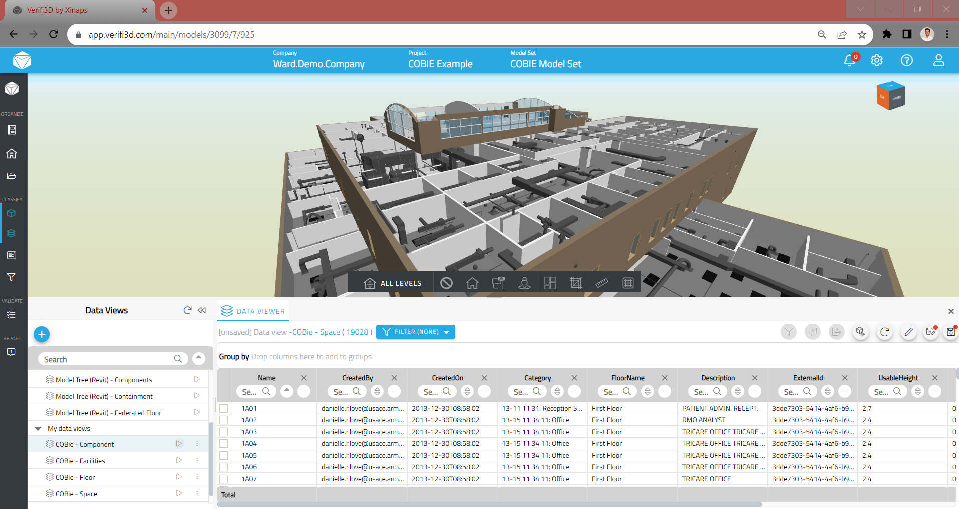
Verifi3D can be used to create COBie sheets. The developers are also looking to create further out-of-the-box COBie capabilities

Beyond the graphical elements of Verifi3D, this release offers powerful new Data View property tools for creating model filter sets. A new table view of elements can be edited to display userdefined table views of the elements in a federated model, based on categories that can be sorted, grouped and coloured to quickly achieve the desired filtered view or for isolation for export. This is useful for creating quantity take-offs, for example, and also ideal for creating COBie sheets. The Verifi3D team is working on expanding this capability to create further out-of-the-box COBie and IDS capabilities.

Verifi3D is fast becoming the Swiss Army knife for BIM data and its goal of replacing Navisworks, Solibri and some CDEs is starting to look pretty attainable

Martyn Day

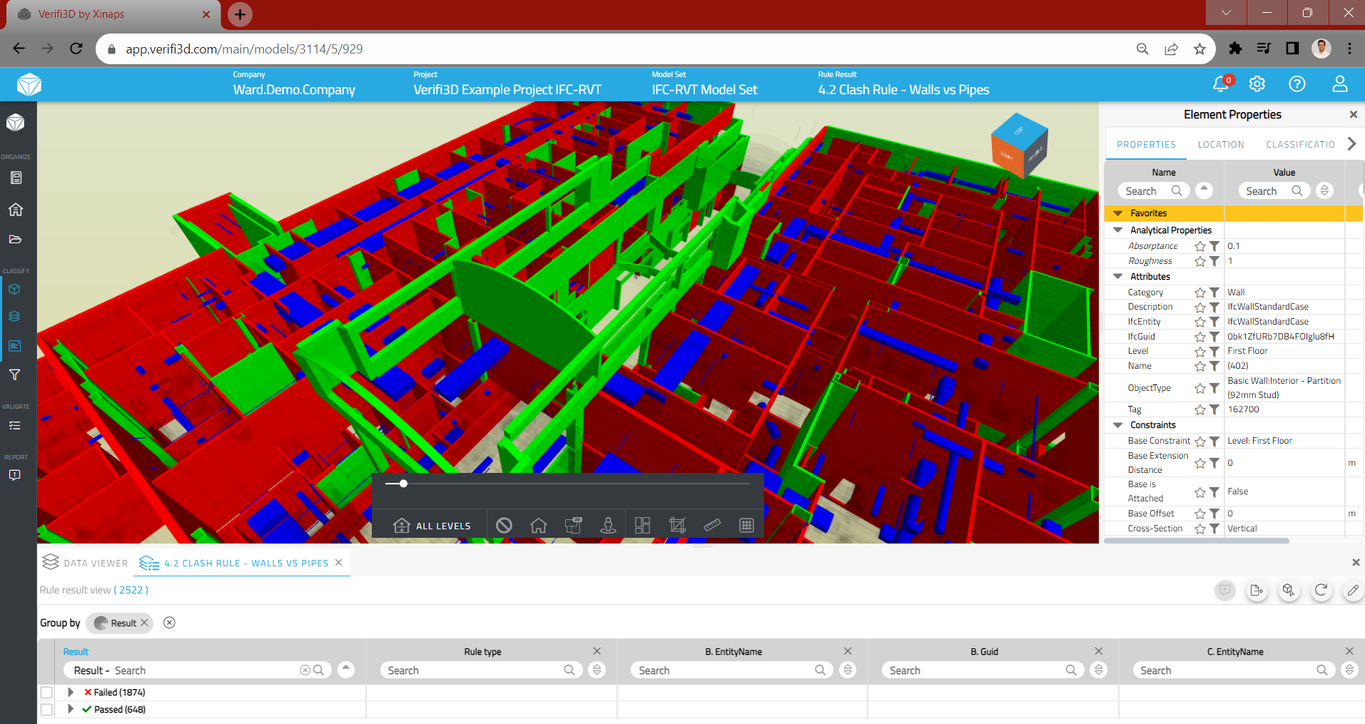
One of the main enhanced features for Verifi3D is its clash detection capability. This can perform clash detections between one or more building objects within a BIM model, helping to identify potential issues early in the design process.

Clashes can be seen in 3D and 2D. They can be hard clashes, or ones based on defined tolerances. Verifi3D also offers a flexible reporting function, which collates results from all verification tests run and the resulting reports can be exported in various formats for easy sharing and collaboration.

Verifi3D is probably the easiest to use application for designing validation checks for models, in order to quickly identify inefficiencies, discrepancies and duplications. These checks can be individual or based on a collection of rules, such as object attributes, classifications, families and parameters. Guidelines and rule sets are crafted in XML format and can be either exported from or imported into Verifi3D for sharing and reuse. Everybody can use the same rules and can be used on Revit and IFC at the same time.

One important point to note is that Verifi3D doesn’t offer built-in issue tracking. According to Schuyer, issue tracking is something that most CDE offerings already provide. In other words, it’s a commodity feature – so Verifi3D is happy to integrate with those CDEs that already offer it, enabling customers to make their own choice.

Conclusion

As a cloud application, it’s not always obvious when Verifi3D has undergone major work. By its nature, it’s constantly under development. But this time around, there have been some big architectural changes in order to overcome previous performance limitations. At the same time, the team has gone even deeper into functionality, providing more advanced ways to filter, validate and generate reports.

In this latest release, it’s clear there has been a lot of work done on the non-visual side of filtering and generating data views from federated models. This opens up new possibilities for Verifi3D in quantity takeoff, reporting and more flexible COBie delivery. Verifi3D is fast becoming the Swiss army knife for BIM data and its goal of replacing Navisworks, Solibri and some CDEs is starting to look pretty attainable. To find out more, there is a 14-day free trial.

Contributor

Director, Editor and Journalist
AEC Magazine

Note: Original article can be accessed here: https://aecmag.com/software/verifi3d-model-checking-validation/

Verifi3D: Leading the way in model checking

Verifi3D: Leading the way in model checking

Good quality data plays an imperative key role in a world where construction projects are becoming increasingly complex, and in which digital technology is being embedded to create a more resilient future. The number of tools that help create, manage, and consume your data is also increasing. Model checking is the key component, and Xinaps is the expert in this process. Xinaps’ flagship solution thrives in digital environments, and Verifi3D revolutionizes how big data is managed with new standards, building codes, and evolving design processes.

Companies that embrace Building Information Modeling (BIM) often invest heavily in Common Data Environments (CDEs), a central repository where all project information is collected, managed, and shared. Building design data is complex and the value of the CDE depends on the quality of the data. In an industry where data is often siloed and fragmented, the use of manual model checking processes results in data inconsistency.

Data quality is the key

The success of construction projects depends on the accuracy and reliability of data. Data is refined into information that is shared across the project team and applied as knowledge to best practice. If data in the CDE does not meet the requisite quality standards, the consequences can cause significant delays and financial losses: inconsistent data can lead to expensive remediations, budget burning delays, and inaccurate decision-making.

The European approach to BIM standardization emphasizes the importance of automated data validation and acknowledges model checking as a critical factor for achieving, for example, environmental sustainability goals. Decision makers, whether individuals or teams, make strategic decisions based on a range of key performance indicators and factors, such as budget, schedule, human and materials resources, and usable information. People need technological support to make objective, well-thought-out decisions. This is where Verifi3D becomes a core tool.

The promise of BIM control

Model checking tools increase the value of data hosted in the CDEs. Model checkers run well defined rule engines to thoroughly check what is in the BIM model and what is hosted in supportive project documents. They provide detailed reports and summaries that ensure the project complies with applicable standards, codes, and regulations.

Legacy model checking tools struggle with different data formats. They often offer limited functionalities and require deep end-user expertise. Lack of knowledge might make design process validation difficult, and checking errors can lead to rework and delays. Additionally, legacy tools often run as desktop applications, which limits real-time collaboration and mobility in hybrid work. The limited integration options with other systems pose an additional budget challenge.

Errors and risks in the construction process are becoming more difficult to prevent and resolve with legacy tools that require manual input and output. The labor heavy processes lead to stretched project lead times and additional costs, as people are manually identifying and correcting building design errors. Moreover, manual validation work hinders smooth cooperation between different stakeholders in construction projects because people are spending time on non-value-adding work.

Transitioning to the future with Verifi3D

Xinaps takes construction project data control to the next level with Verifi3D. Verifi3D is showcasing unmatched power in model checking and the end-user experience. The platform improves collaboration between different stakeholders and introduces the most effective approach to BIM data validation. Verifi3D is a cloud-based solution that supports multiple file formats and provides seamless integration with leading CDEs. Verifi3D becomes a user-friendly single source of truth for the entire project team. Anyone involved in the building design process can get started quickly as the solution is accessible and does not require extensive training. Verifi3D is extremely fast at loading design models and has a powerful viewer with a handy filter function and an advanced rule-based search engine. Verifi3D makes it easy to detect model clashes and optimize the project workflow.

In an industry where speed, efficiency and collaboration are essential, Verifi3D stands at the forefront of digital transformation with inclusive collaboration. It is time to welcome next-gen tools and embrace Verifi3D as the new platform for model checking. Let us take the step to the future of construction projects together, empowered with Verifi3D. So, why wait?

Contributor

CEO/Founder
SEE Bright

CEO/Founder
SEE Bright

Digital transformation and the future of the construction industry ft. Verifi3D

Digital transformation and the future of the construction industry ft. Verifi3D

The construction industry is going through a digital transformation and there is a rising demand for better model coordination between various project stakeholders and more emphasis on digital tools and global standards mandated by the government. Traditionally the construction industry has been seen as slow to embrace technological advancements without compelling reasons to do so. However, in recent years, a significant shift has occurred, driven by the need for greater efficiency, reduced costs and improved project outcomes and unlocking opportunities for checking the very models that express the design. This transformation is being powered by digital technology, which is revolutionizing the way construction projects are planned, executed and managed.

Understanding digitization and digitalization in construction

Digital transformations generally take the form of two consecutive stages: the digitization of information is followed by the digitalization of processes. In construction, for example, the paper drawings containing design information were digitized and thus transformed into digital CAD files. A digitized CAD drawing allows for the digitalization of workflows relating to the information a drawing contains, e.g. referencing to digital libraries of objects, design automation through scripting, or tracking of remarks and revisions entirely in digital form. Digital transformation is like a searchlight that lightens up one segment of the construction industry after the other, affecting ever more areas of work through the digitization of information and the digitalization of processes. From tenders to planning to drafting to logistics to costing to billing, one discipline after the other is subject to the same two-step disruption as digital transformation ripples through the industry.

Traditionally, construction projects heavily relied on paper-based drawings and manual model checking processes. This approach was time-consuming, prone to errors, and often resulted in clashes and compliance issues and data inconsistencies being discovered late in the construction process. Such issues could lead to costly delays and rework and impact the quality of the building design models and data. But moving towards digital drawings also brought the perspective of replacing manual model checking with automated model checking. This shift can be seen as a “Push/Pull” dynamic, where various factors are driving the industry to adopt digital technology while simultaneously pulling it away from analogue workflows.

Model checking to the rescue

As modern construction projects are becoming increasingly complex with a multitude of stakeholders relying on desktop point solutions, it results in inconsistent building data and processes. The problem at hand necessitates the use of more sophisticated tools to manage intricate designs and model checking processes. Project timelines are often tight, teams are under constant pressure to check multiple models of varying file formats and sizes, reduce costs and optimize resource utilization which pushes toward a need for an efficient building design process. These challenges have indeed made it imperative for the industry to adopt more advanced tools to streamline building design processes and ensure project success all the while maintaining the quality of the building design data. All this makes automated model checking a critical component of digital transformation in construction.

Effective model checking involves the classification, verification and validation of building design models to ensure they are accurate, clash-free and compliant with building codes and regulations. To implement it in the building design process, it is essential to identify authoritative solutions and tools. One such solution is Verifi3D which stands at the forefront of digital transformation. As the next-generation model checking solution that uses predefined templates based on connected and openBIM workflow, Verifi3D with its advanced rule-based engine automates clash, geometric and parametric checking all in a browser-based environment.

Construction project interoperability and ISO 19650 compliance

To ensure consistency and best practices, many construction projects adhere to established industry standards. OpenBIM promotes interoperability and collaboration among various stakeholders involved in a construction project. Verifi3D’s flexibility and interoperability as an openBIM and connected solution ensure that digital models can be seamlessly shared, enhancing compatibility and reducing the risk of data loss or errors during the exchange of information. With its advanced rule-based engine, Verifi3D allows users to define custom filters, rules and checks based on local building codes, standards and project-specific requirements. This standardization of process enhances interoperability and facilitates a seamless flow of information, thus ensuring an automated and optimized building design workflow.

Moreover, in many regions, construction projects must adhere to specific building codes and regulations. ISO 19650 is an international standard for managing information over the entire life cycle of a built asset. Verifi3D supports the principles of information management defined in ISO 19650, such as the organization and classification of data, version control and data exchange/viewing protocols. With version control, Verifi3D ensures that all project stakeholders are working with the latest and most compliant versions of building design models. This is crucial for maintaining ISO 19650 compliance, as it helps prevent data inconsistencies and confusion related to outdated and inconsistent information among stakeholders.

Shaping the future of construction

The construction industry is entering a new era of digital transformation where efficiency, accuracy, and collaboration are paramount. Model checking with the help of a next-generation tool like Verifi3D, plays a central role in this transformation. By automating clash, geometric and parametric checks and offering advanced next-gen machine learning capabilities, Verifi3D is at the forefront of shaping the future of construction ensuring that all project stakeholders are working with synchronized and compatible digital models of the project. As the industry continues to evolve, embracing digital transformation and innovative solutions will be key to achieving success in construction projects of all sizes and complexities. Ultimately, by automating model checking, the construction industry can reduce errors, streamline processes and most importantly deliver projects on time and within budget at the highest quality.

Contributors

Product Owner
Verifi3D by Xinaps

Milu Sini Lal

Marketing Executive
Verifi3D by Xinaps

Product Owner
Verifi3D by Xinaps

Milu Sini Lal

Marketing Executive
Verifi3D by Xinaps

How to connect Verifi3D with BIMcollab?

How to connect Verifi3D with BIMcollab?

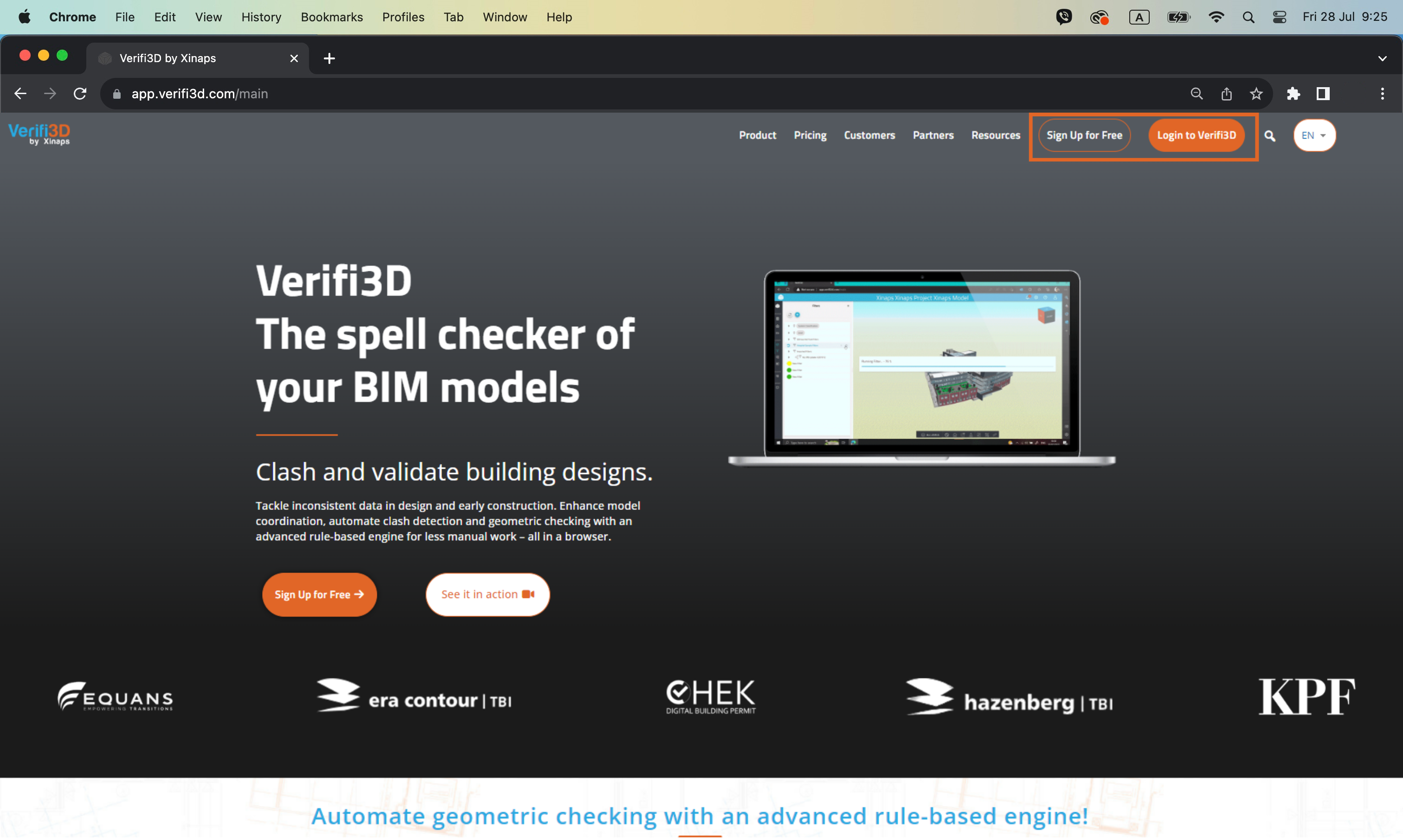
1. Navigate to the login and sign up page

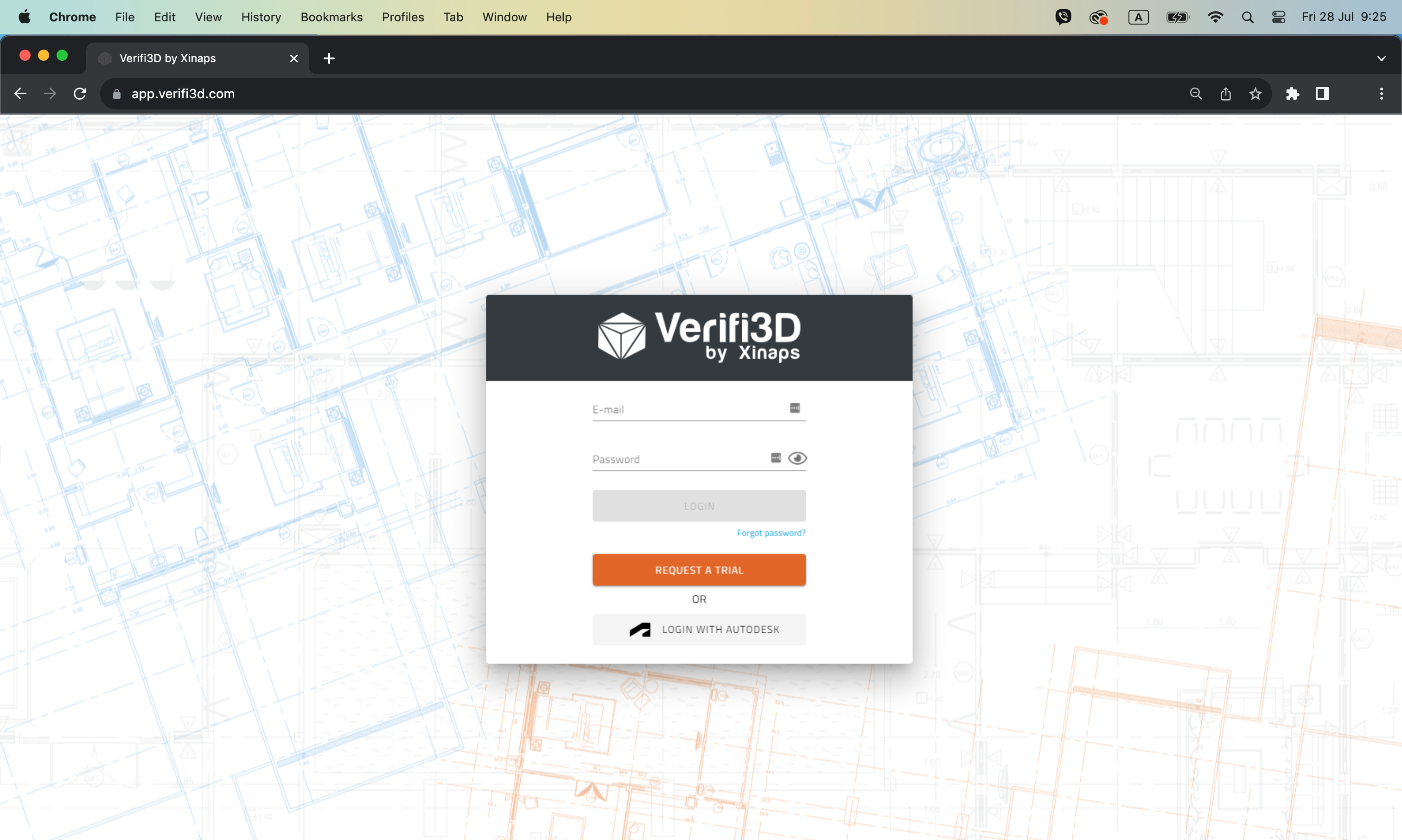
2. Sign up for a new account or log in to Verifi3D with your Verifi3D credentials

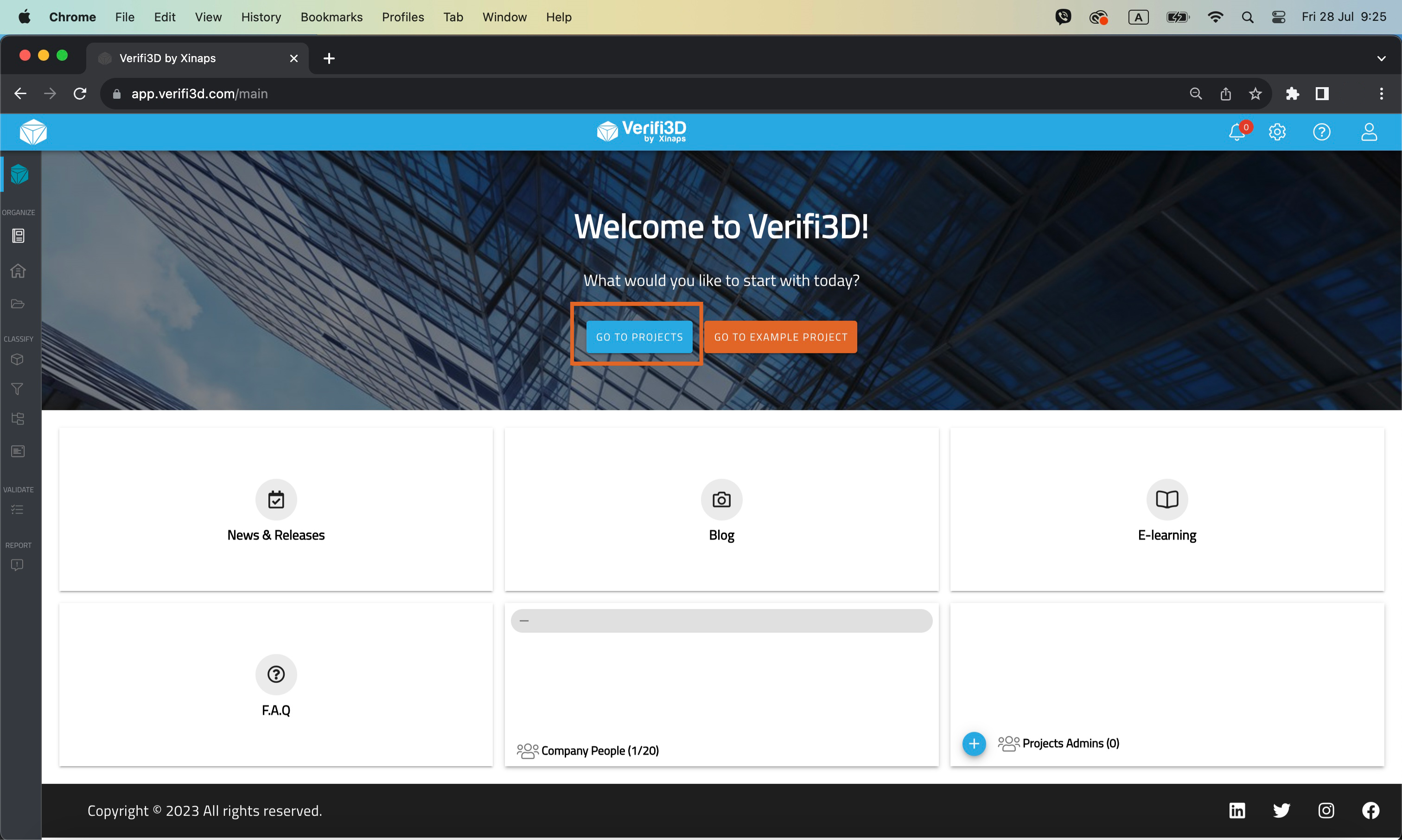
3. To see the Projects overview page, click on the “Go To Projects” button

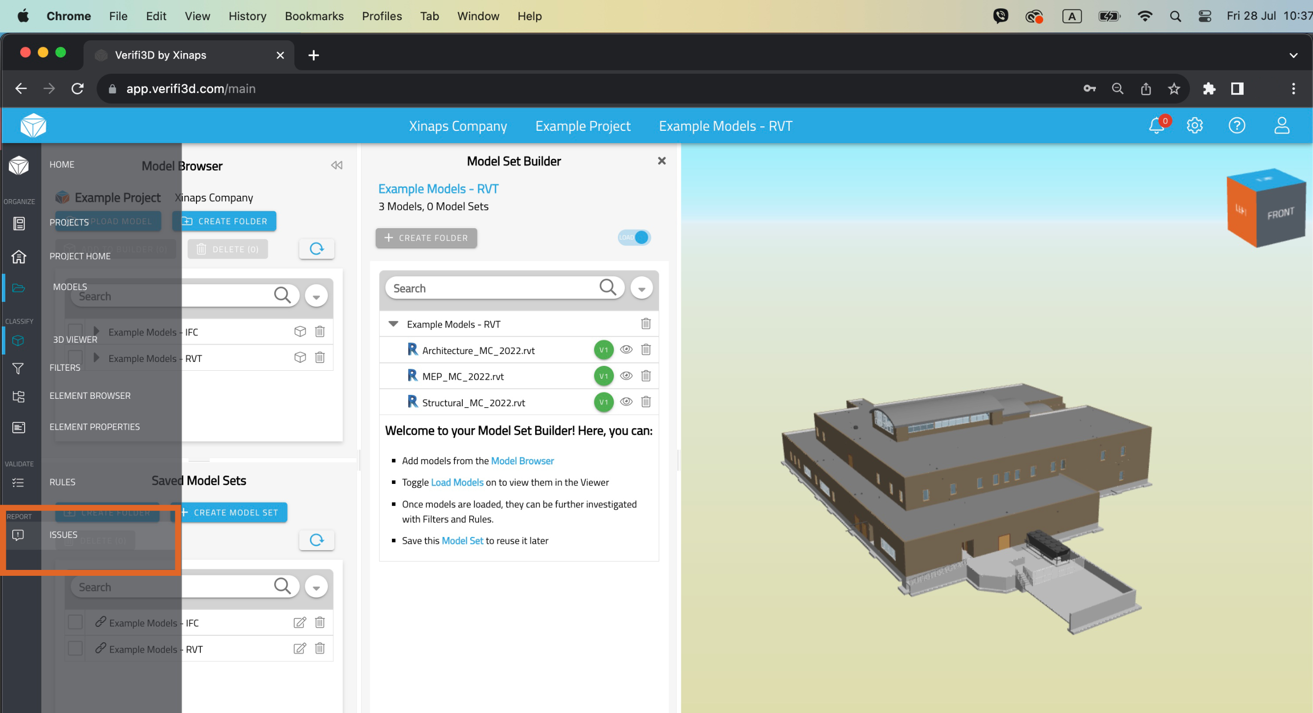
4. Load the Model/ModelSets into the 3D Viewer

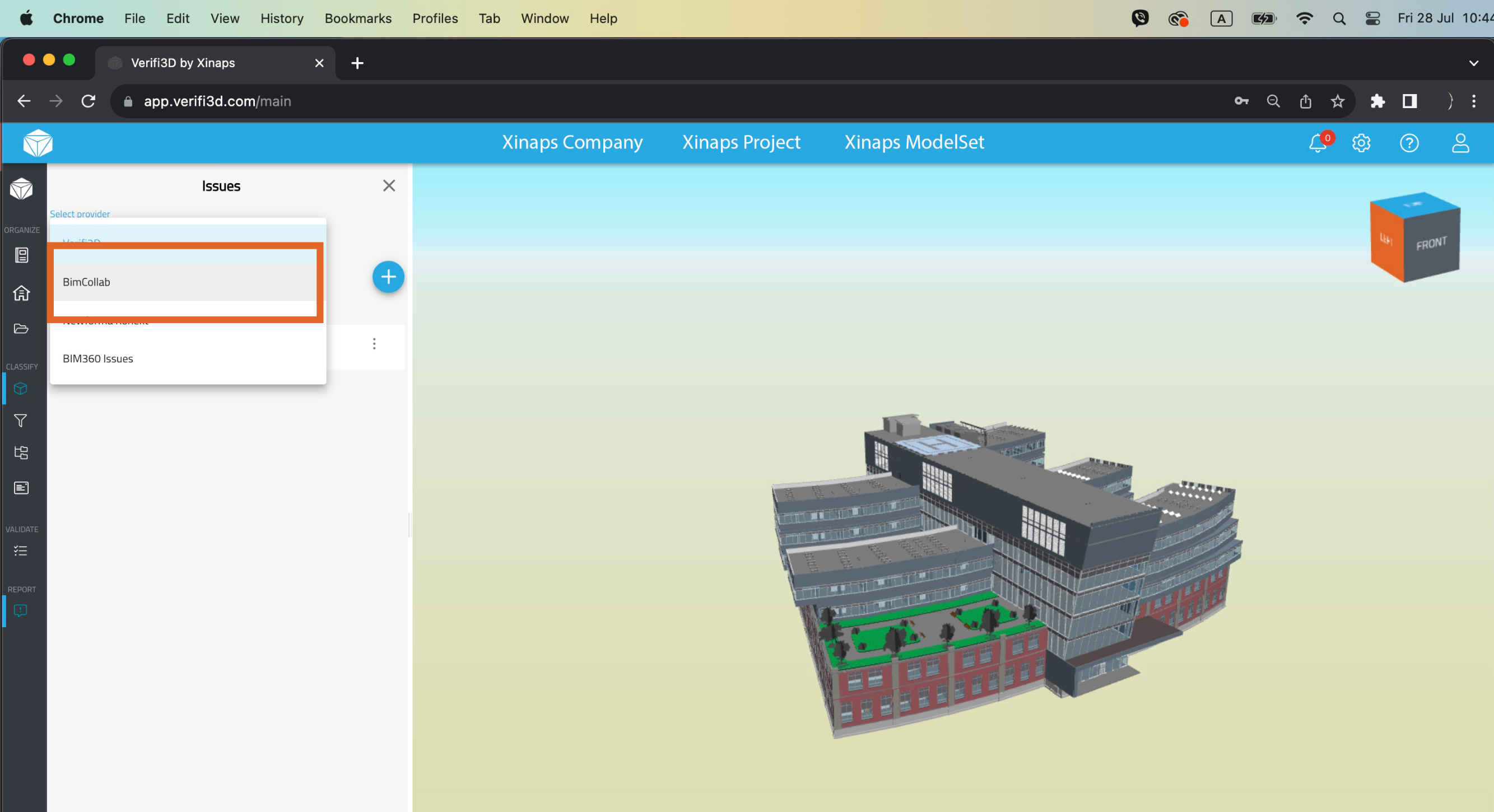
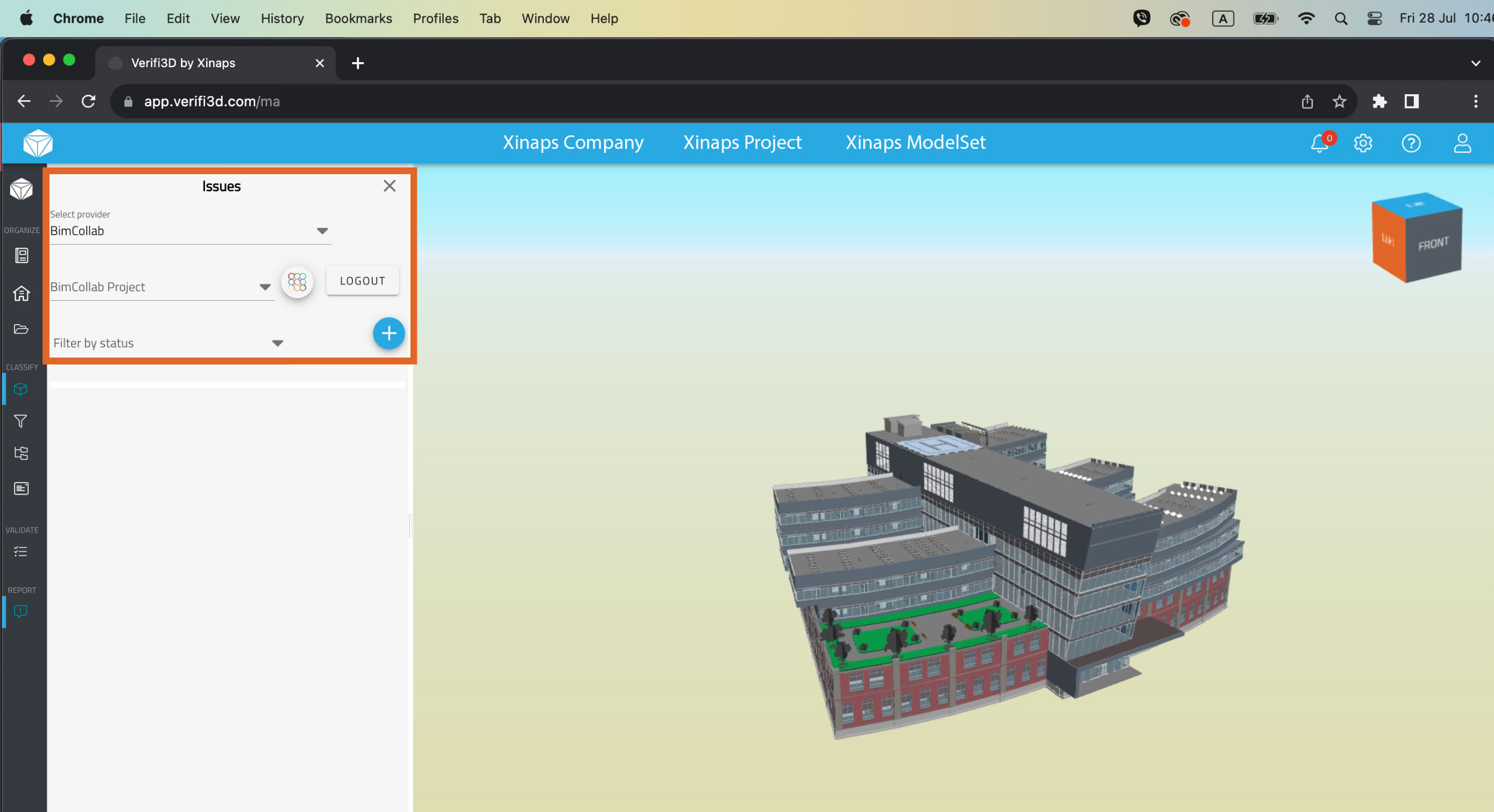
5. Click on the issues button to open the issues panel and click on the drop button and select “BIMcollab”

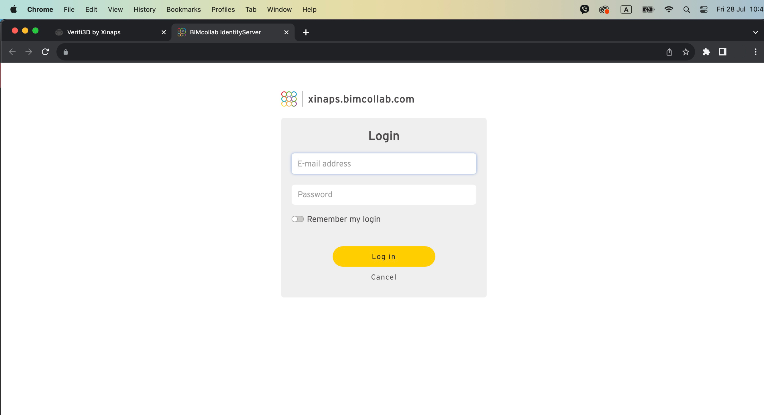
6. You will need to authenticate yourself with your BIMcollab credentials

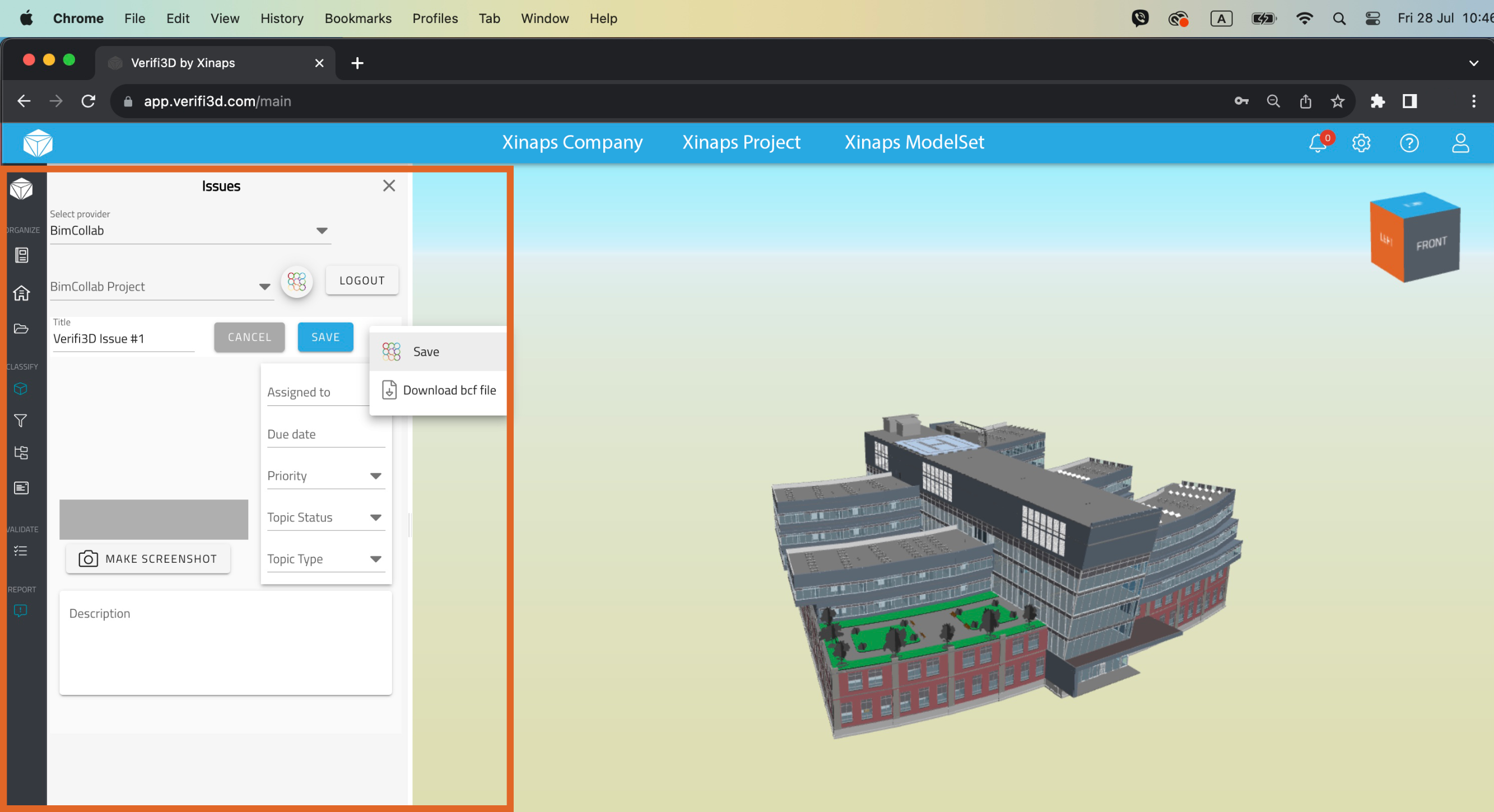
7. Once authenticated, your BIMcollab projects will automatically appear in the Verifi3D environment. You can create a new issue or load an existing issue from BIMcollab. You can add all the necessary details such as priority, issue date, assigned to person, desciption and add screenshot(s).

8. You can download the issues as a BCF file.

Don't miss out on our exclusive bundle package!

Contact us today to receive a proposal and take advantage of our Verifi3D and BIMcollab integration!

Contact us today to receive a proposal and take advantage of our Verifi3D and Dropbox integration!

Contributor

Milu Sini Lal

Marketing Executive
Xinaps

Milu Sini Lal

Marketing Executive
Xinaps

How to connect Verifi3D with Newforma Konekt?

How to connect Verifi3D with Newforma Konekt?

1. Navigate to the login and sign up page

2. Sign up for a new account or log in to Verifi3D with your Verifi3D credentials

3. To see the Projects overview page, click on the “Go To Projects” button

4. Load the Model/ModelSets into the 3D Viewer

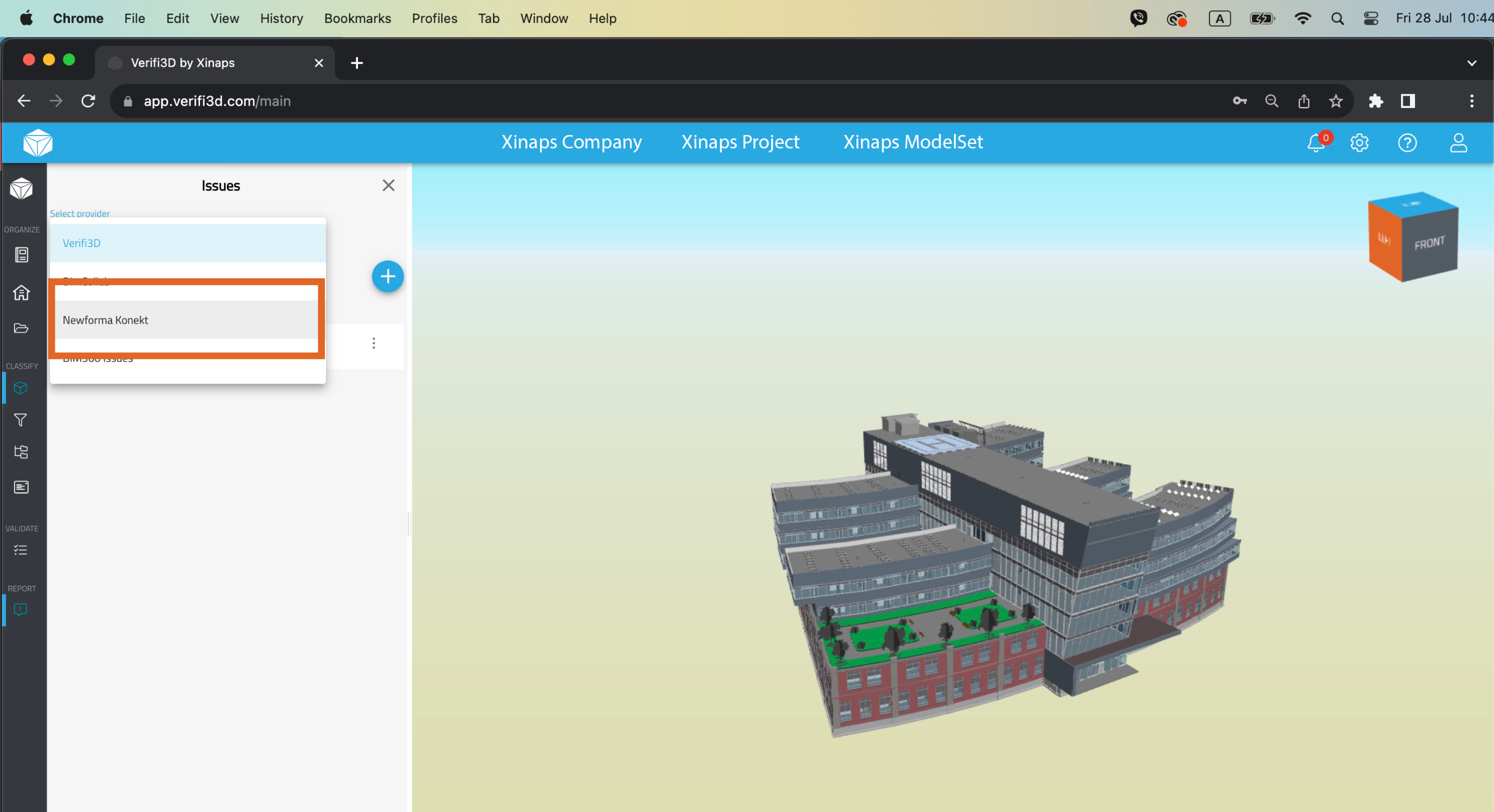
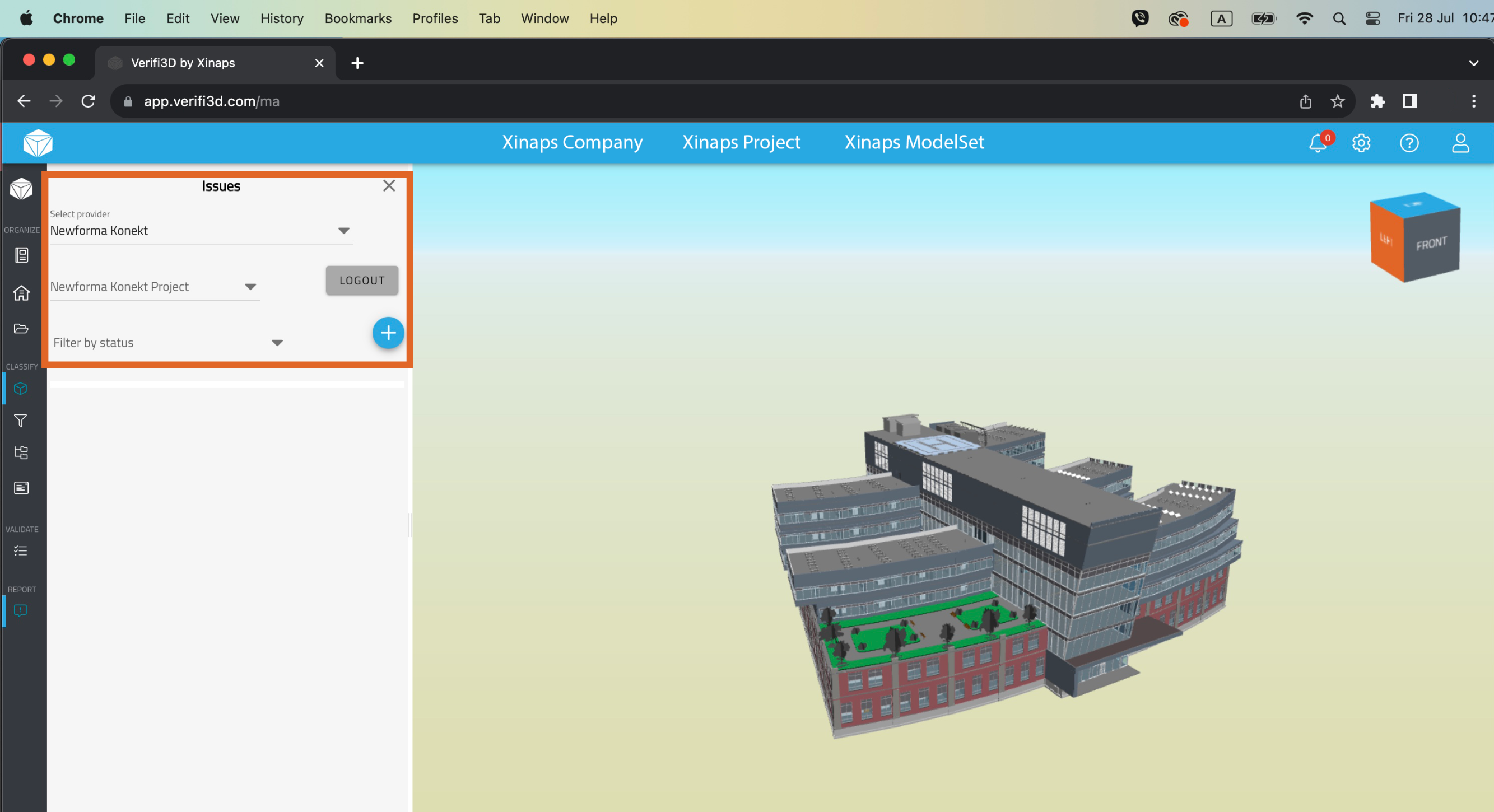
5. Click on the issues button to open the issues panel and click on the drop button and select “Newforma Konekt”

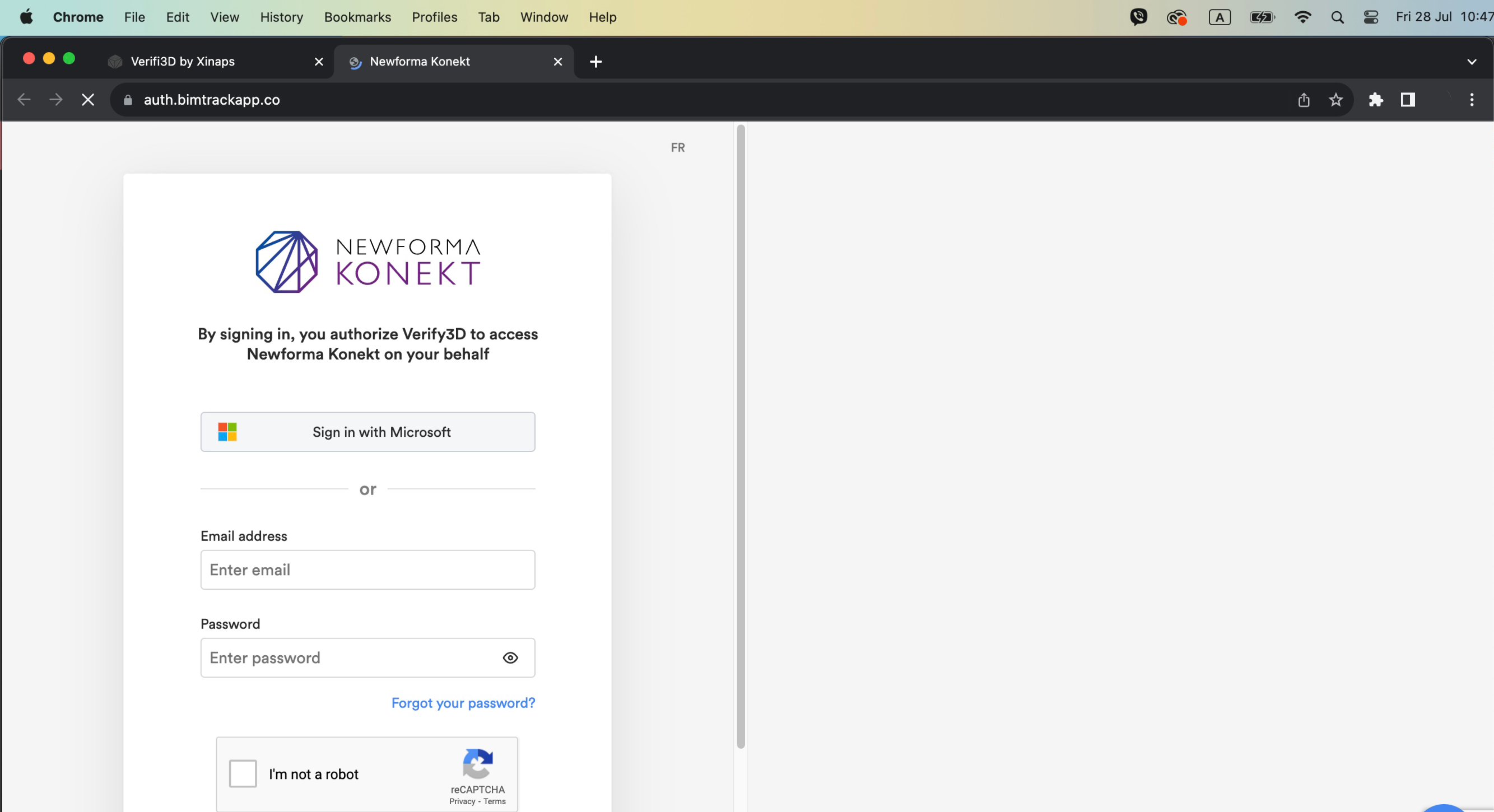
6. You will need to authenticate yourself with your Newforma Konekt credentials

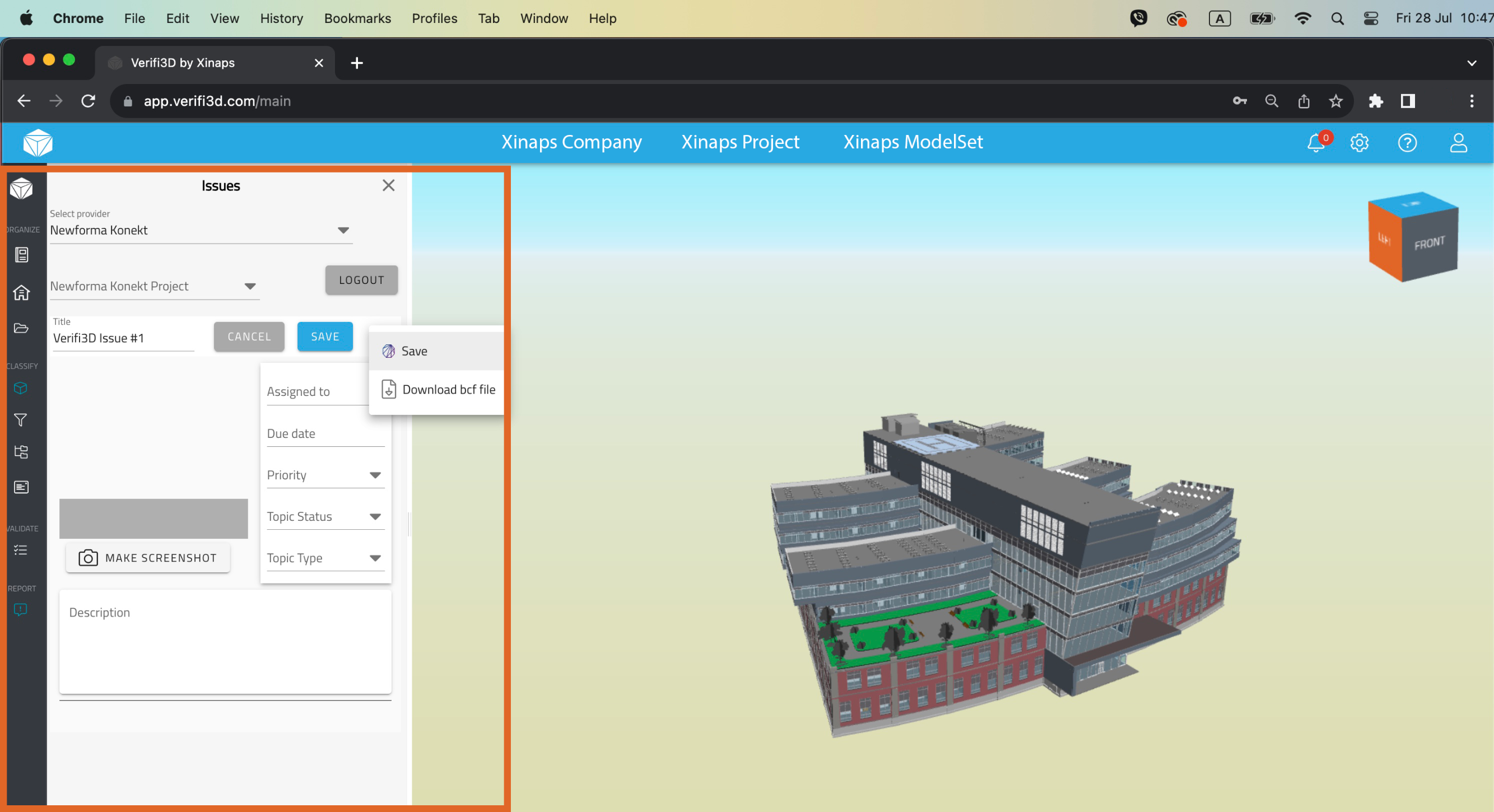
7. Once authenticated, your Newforma Konekt projects will automatically appear in the Verifi3D environment. You can create a new issue or load an existing issue from Newforma Konekt. You can add all the necessary details such as priority, issue date, assigned to person, desciption and add screenshot(s).

8. You can download the issues as a BCF file.

Don't miss out on our exclusive bundle package!

Contact us today to receive a proposal and take advantage of our Verifi3D and Newforma Konekt integration!

Contact us today to receive a proposal and take advantage of our Verifi3D and Dropbox integration!

Contributor

Milu Sini Lal

Marketing Executive
Xinaps

Milu Sini Lal

Marketing Executive
Xinaps

How to connect Verifi3D with Autodesk BIM 360 Issues?

How to connect Verifi3D with Autodesk BIM 360 Issues?

1. Navigate to the login and sign up page

2. Sign up for a new account or log in to Verifi3D with your Verifi3D credentials

3. To see the Projects overview page, click on the “Go To Projects” button

4. Load the Model/ModelSets into the 3D Viewer

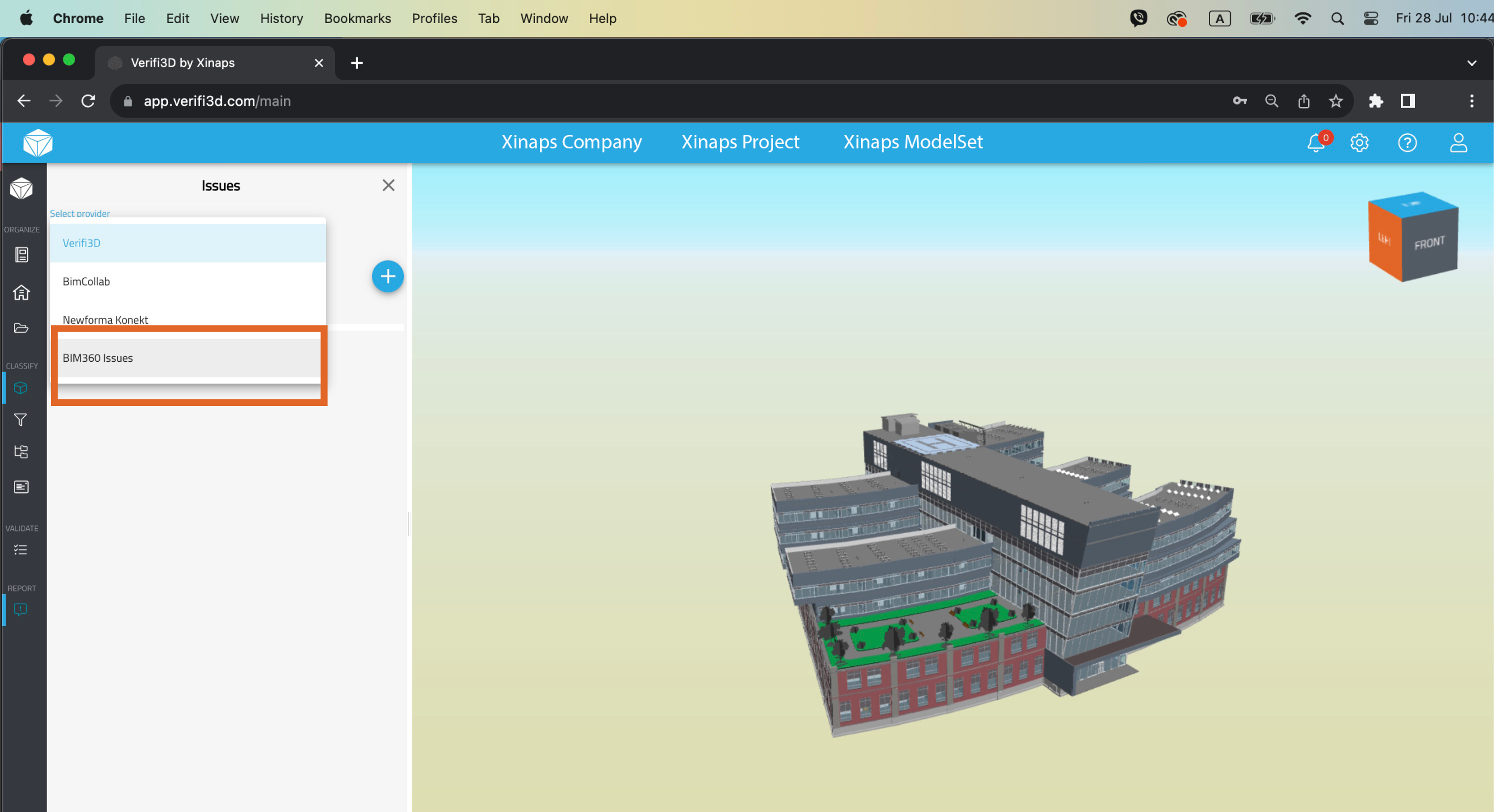
5. Click on the issues button to open the issues panel and click on the drop button and select “Autodesk BIM 360 Issues”

6. You will need to authenticate yourself with your Autodesk BIM 360 Issues credentials

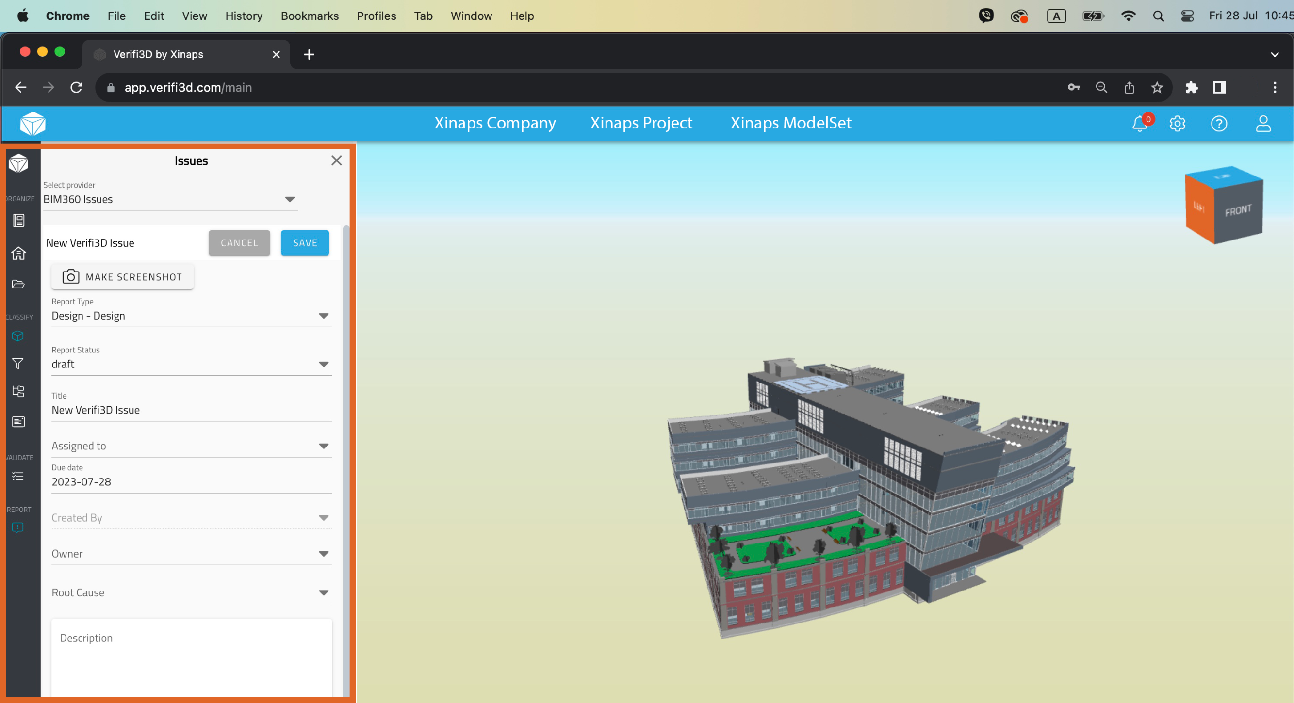
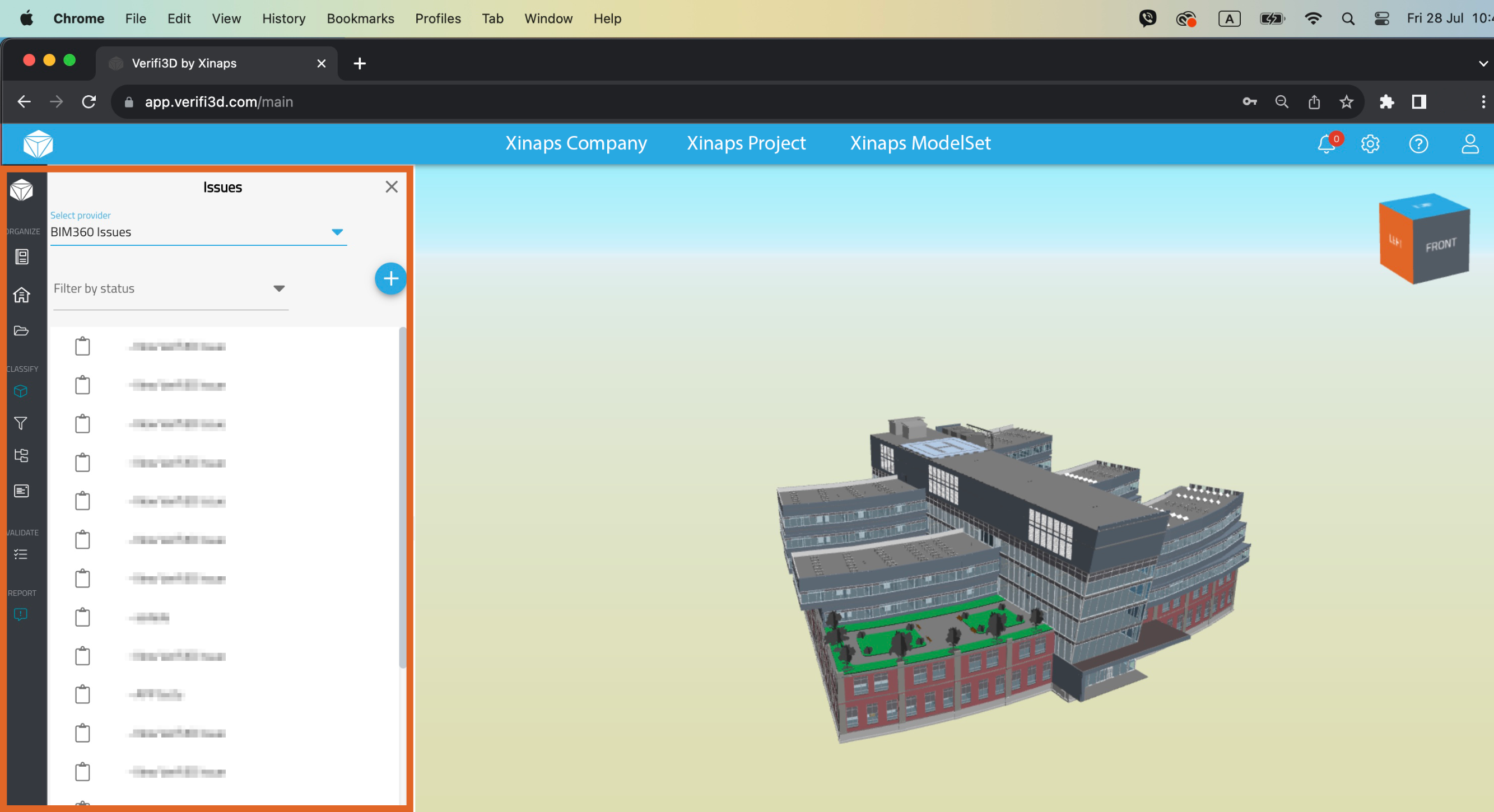
7. Once authenticated, your Autodesk BIM 360 Issues projects will automatically appear in the Verifi3D environment. You can create a new issue or load an existing issue from Autodesk BIM 360 Issues. You can add all the necessary details such as priority, issue date, assigned to person, desciption and add screenshot(s).

8. You can download the issues as a BCF file.

Don't miss out on our exclusive bundle package!

Contact us today to receive a proposal and take advantage of our Verifi3D and Autodesk BIM 360 Issues integration!

Contact us today to receive a proposal and take advantage of our Verifi3D and Dropbox integration!

Contributor

Milu Sini Lal

Marketing Executive
Xinaps

Milu Sini Lal

Marketing Executive
Xinaps

How to connect Verifi3D with Autodesk BIM 360?

How to connect Verifi3D with Autodesk BIM 360?

1. Navigate to the login and sign up page

2. Sign up for a new account or log in to Verifi3D with your Verifi3D credentials

3. To see the Projects overview page, click on the “Go To Projects” button

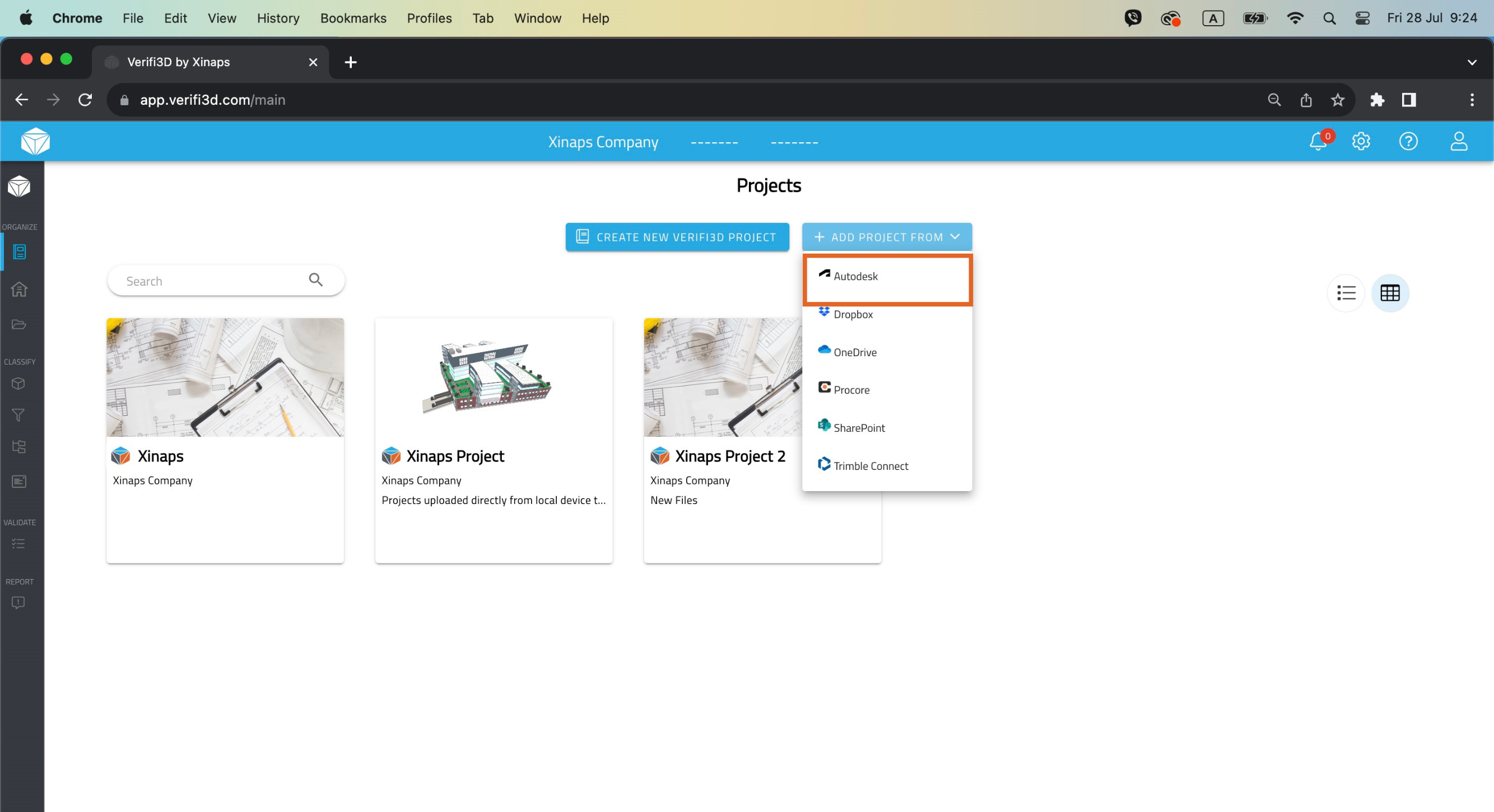
4. Click on the button “Add Project From” and from the dropdown select “Autodesk”

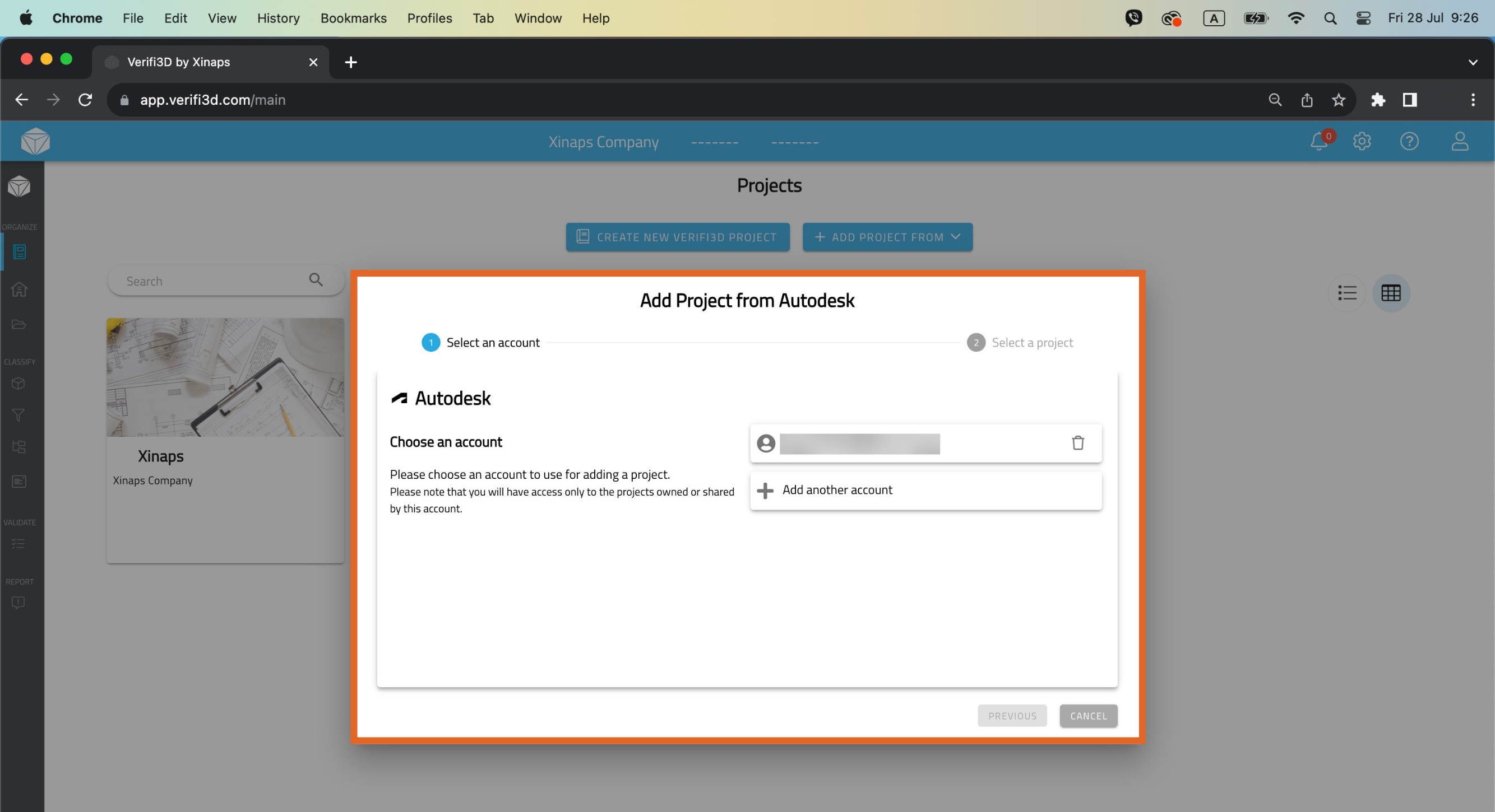
5. You will need to authenticate yourself with your Autodesk credentials

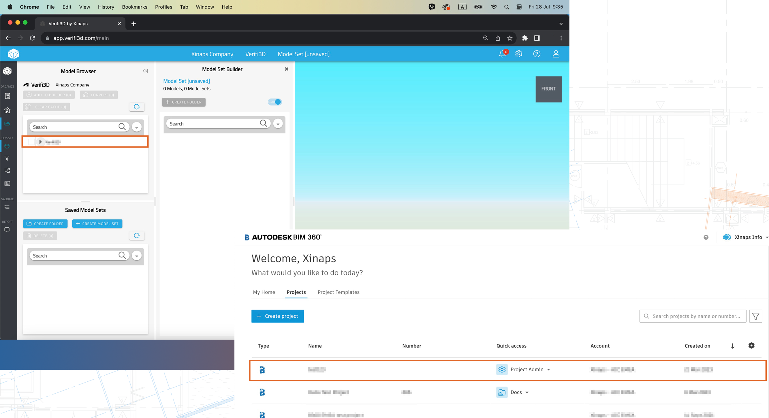
6. Once authenticated, your Autodesk BIM 360 projects will automatically appear in the Verifi3D environment

7. You can find the content of your Autodesk BIM 360 in Models > Model Browser.

Don't miss out on our exclusive bundle package!

Contact us today to receive a proposal and take advantage of our Verifi3D and Autodesk BIM 360 integration!

Contact us today to receive a proposal and take advantage of our Verifi3D and Dropbox integration!

Contributor

Milu Sini Lal

Marketing Executive
Xinaps

Milu Sini Lal

Marketing Executive
Xinaps